1. How to Test Successful Hardware Setup and Configuration
This guide provides detailed information on how to confirm successful set up and operation. We will cover the following:

All Per Vices products are tested and confirmed to work prior to shipping; this guide describes how to test and confirm product operation. Where feasible, it also provides references or support for how to address or fix a particular section if it isn’t working as it should.
1.0. Initial Power On Test
The first test can occur immediately after you plug in the unit to power. After turning the unit on, using the power switch, you should be able to see and hear the cooling rapidly spin up. If you do not see the cooling fans, confirm the outlet has power and the cord is undamaged.
Warning
 |
The chassis fans are meant to draw air into the unit: Do not attempt to confirm operation by touching or obstructing air inlet. |
Note
We strongly recommend using a power protection device, such as a power bar or Uninteruptable Power Supply (UPS), when providing power to Per Vices Software Defined Radio Products. We also strongly recommend connecting the chassis grounding lug to an external common ground. If you have any questions or concerns about providing power to our products, contact a certified electrician.
1.1. LED Boot Sequence
The next indication of successful operation is to use the four status LEDs to check proper device operation. After power is provided, and the device turned on, the four status LEDs next to the SD card will begin to light up. A normal LED sequence is shown in Table 1.
Table 1: Per Vices Status LEDs Normal Boot Sequence
| Figure | Stage | Description |
|---|---|---|
 |
a | Device is powered on |
 |
b | FPGA is operating with a stable clock |
 |
c | FPGA is up and Linux is booting |
 |
d | HPS is up and Linux has booted |
 |
e | Server is booting up |
 |
f | Server has booted up |
The very first time you plug in the product, it may take longer than normal to completely boot. We suggest waiting up to 180s for the initial boot to complete. Subsequent boots are usually faster.
Once your product reaches the stage f LED sequence, it is fully booted and ready for use!
1.2. Ping Test
The ping test is a very useful and basic test that confirms your computer can successfully send and receive data over the management and data ports of the Software Defined Radio.
Note
Run this test across each individual connected management and data port to independently verify the connectivity and operation of each cable. Proper operation requires that the host machines have a connection to at least one management port, and ALL data ports on the product.
This basic test serves to check if a route exists between your host computer and the specified IP address. The Crimson Networking or Cyan Networking specification pages provide the default management and data port IP addresses.
You will want to conduct a basic ping test on each of the management and data IP addresses. Assuming that the address you want to test is W.X.Y.Z, you can run this test by typing the following into a terminal:
Figure 1: Ping Test
[host_pc]$ ping W.X.Y.Z -c 3The expected output from a successful ping test is shown below:
Figure 2: Successful Ping Test
PING W.X.Y.Z (W.X.Y.Z) 56(84) bytes of data.
64 bytes from W.X.Y.Z: icmp_seq=1 ttl=64 time=0.912 ms
64 bytes from W.X.Y.Z: icmp_seq=2 ttl=64 time=0.917 ms
64 bytes from W.X.Y.Z: icmp_seq=3 ttl=64 time=0.917 ms

--- W.X.Y.Z ping statistics ---
3 packets transmitted, 3 received, 0% packet loss, time 2.746ms
rtt min/avg/max/mdev = 0.912/0.915/0.917/0.019 ms
Note
Make sure the letters “W”, “X”, “Y” and “Z” are replaced with their respective numbers from the IP Address. The Crimson Networking or Cyan Networking specification pages provide the respective IP addresses.
This result means you have confirmed basic connectivity between the host pc and the radio for the specified IP address.
If your network is incorrectly configured, or you are otherwise unable to establish a network connection between the radio and the product, you may see the following result;
Figure 3: Failed Ping Test
PING 192.168.10.2 (192.168.10.2) 56(84) bytes of data.
From A.B.C.D icmp_seq=1 Destination Host Unreachable
From A.B.C.D icmp_seq=2 Destination Host Unreachable
From A.B.C.D icmp_seq=3 Destination Host Unreachable

--- 192.168.10.2 ping statistics ---
3 packets transmitted, 0 received, +3 errors, 100% packet loss,
time 2013ms
A failed ping test indicates a failure in the networking connection between the host PC and the target IP address on the Software Defined Radio. Confirm the host network configuration, and that your network topology matches that shown on the Crimson Networking or Cyan Networking pages.
If you continue to encounter errors, confirm the problem isn’t with the cables or network cards themselves, by either swapping cables or ports with one that is known to work.
Note
In order to use the device, you must ensure that each port successfully passes the ping test.
1.2.1 Example Ping Test
As an example, if you wanted to ping the SFP+ A port which we set up in this example, you would use the following to ping the associated IP address:
[host_pc]$ ping 10.10.10.2 -c 31.3. UHD Test
Following a successful ping test, and after setting up UHD and gnuradio, and installing the Per Vices UHD library and GNURadio, you are ready to test the operation of UHD.
This test will ensure that the Per Vices UHD hardware drivers are setup correctly and pass a simple UHD test, as shown in Figure 4. This is the first test to determine whether UHD is capable of finding the Per Vices SDR device. It’s worth running this test twice; the first time by specifying the management IP address, and the second time without. In a correct configuration, with a single SDR device, you should be able to automatically find the device without specifying the address.
To run this test, and assuming the management IP address is 192.168.10.2, type the following:
Figure 4: UHD Test
[host_pc]$ uhd_find_devices --args 'addr=192.168.10.2'The output from a successful uhd_find_devices test will be similar to the following output:
Figure 5: Successful UHD test
[INFO] [UHD] linux; GNU C++ version 13.2.1 20230801; Boost_108300; UHD_4.4.0.makepkg-1990-g0292ef80
--------------------------------------------------
-- UHD Device 0
--------------------------------------------------
Device Address:
serial: 001
addr: 192.168.10.2
name:
type: crimson_tng
The output from a failed test will show the following output:
Figure 6: Failed UHD test
Linux; GNU C++ version 6.3.1 20170306; Boost_106300;
UHD_003.008.000-382-gef596087

Error: LookupError: KeyError: No devices found for ----->
Device Address:
addr: 192.168.10.2
If the command in Figure 4 works, try running it again without specifying the address;
[host_pc]$ uhd_find_devicesIf this command is successful, you will see the same successful output as before. If it fails, you will see something similar to this:
Linux; GNU C++ version 6.3.1 20170306; Boost_106300;
UHD_003.008.000-382-gef596087

No UHD Devices Found
This is an indication that UHD is unable to detect your radio. When this happens, the first thing to check is the wiring: make sure the device is plugged in correctly.
Next, confirm that the network settings specified for Crimson TNG in Table 1, Table 2, and Figure 6 are correct. If you are using Cyan, consult Table 1 and Table 2, and confirm the network settings.
Pay special attention to the network configuration page, and in particular the routing table configuration.
Finally, check to see whether any firewalls are enabled, and, if so, configure them accordingly. If using Oracle, or SELinux, you may also want to review the corresponding openport.sh script.
If this still does not work, please contact us for additional assistance.
1.4. Website Test
This test only applies to Crimson.
The following test is used to determine whether you can access the website. This is helpful to ensure that the IP address you are attempting to reach is, in fact, a Crimson TNG device. To run this test, simply open a browser, and attempt to access the website by typing in the management IP address.
The default IP address of the Crimson TNG MGMT and Cyan MGMT A port is shown below and needs to be written in the address bar of a browser:
192.168.10.2If you are able to successfully access the website, as shown in Figure 7, then you have connected with a Crimson TNG device.
Figure 7: Crimson TNG Website
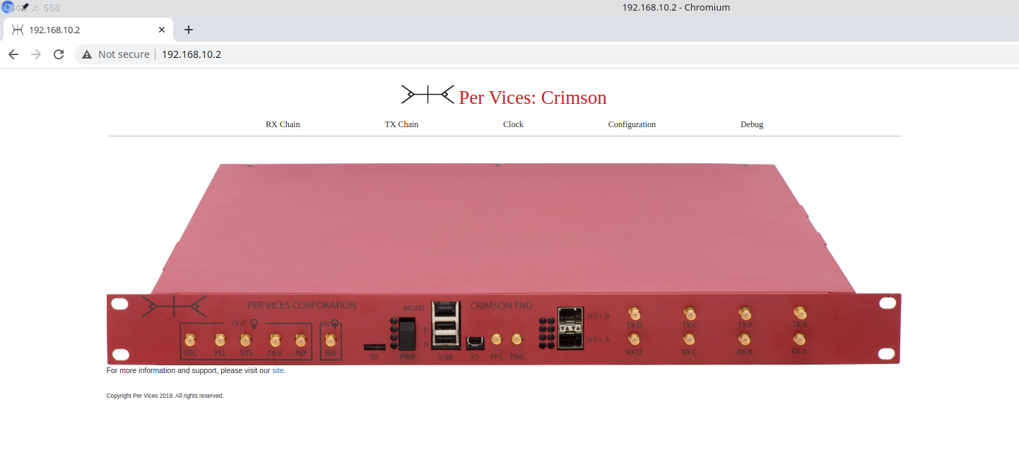
If you are unable to access the website, then double check that you have correctly specified the management IP address, and/or that your netmask is correctly assigned.
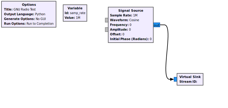
1.5. GNU Radio Test
You will also need to verify that the GNU Radio companion software is in fact correctly installed. A simple way to ensure this is to open up a new GNU Radio project, place a Signal Source block and route this through a Throttle to a QT GUI Frequency Sink block. When this is run a frequency graph should appear; ensure there is no error messages. The GNURadio Wiki is an excellent resource for fixing errors and finding tutorials. This example is shown below:
Figure 8: Simple GNU Radio Test
1.6. Testing the Radio Chain
As a final test, download the following GNU Radio Script to ensure the radio chain is working correctly. In order to run this script properly you will need to set up the unit for a loop back operation; instructions to do this can be found here building your first waterfall plot.
Note
If you are using the wget command
wget https://raw.githubusercontent.com/pervices/releases/master/validation/SimpleShipTest.grc Run the above script in the GNU Radio companion. Your result should be something like this
Figure 9: GNU radio chain test output
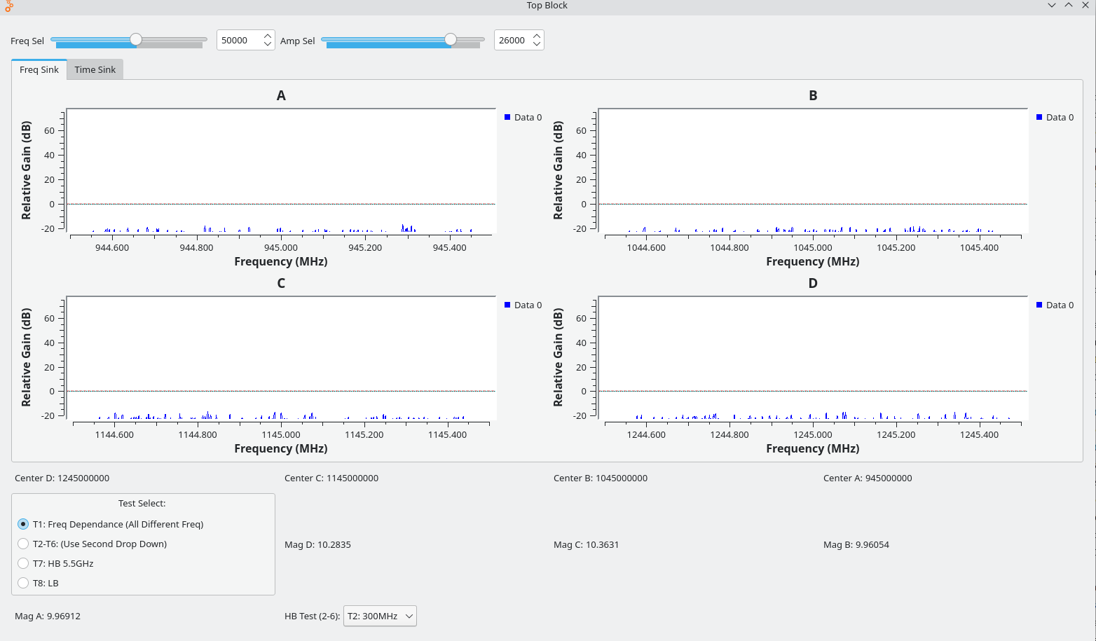
Note
If you have connected loopback cables attached with 30db attenuators from the Tx to Rx of SMA ports A, B, C, and D, you should be able to see signals on the graph.
You can view the building your first waterfall plot tutorial to learn more about GNU Radio.
1.7. Additional Resources
If you would like to become more familiar with using GNU Radio, see the tutorial shown here.