Crimson TNG and Cyan VITA 49 Interface Specification
1. Introduction
The VITA Radio Transport (VRT) standard, also known as the VITA 49 protocol, defines a standardized format for sending/receiving digitized messages between RF systems and related equipment. Per Vices products presently support Standard Signal Data Packets, as defined by the VITA 49 data packet protocol. To send and receive commands between Rx/Tx channels and FPGA/processors, Per Vices uses UHD hardware drivers.
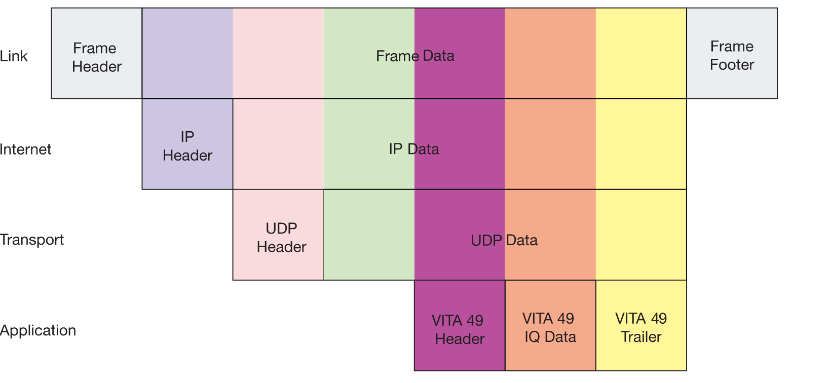
Per Vices uses a data encapsulation which implements VITA 49 within UDP (User Datagram Protocol) within IP within Ethernet (i.e. Application > Transport > Internet > Link), as shown in Figure 1 below.
Figure 1: Per Vices Crimson TNG and Cyan Stack
2. Signal Data Packet Implementation in Per Vices Products
First, we will explain the data encapsulation stack layers in Figure 1. Following this, we will discuss how Tx and Rx data packets are implemented in Crimson TNG and Cyan. To do this, we will use Wireshark to analyze 10 frames captured for both Tx and Rx in order to explain how all layers of Figure 1 are formatted.
2.1. Data Encapsulation Protocols and Formats (Stack)
Link Layer (Ethernet)
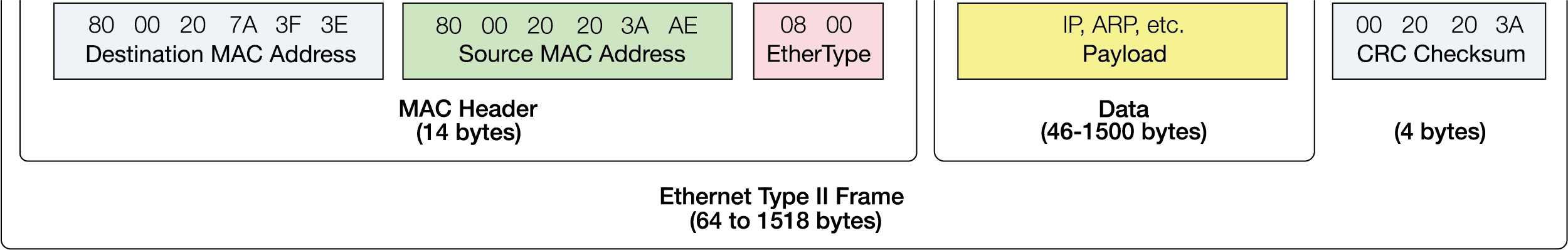
Within the Link layer of Figure 1, an Ethernet stack is present in order to send/receive data from host computer to your device. It is formatted like Figure 8 below. Systems which communicate using Ethernet divide a stream of data into shorter pieces called frames. As you can see in Figure 1, the VITA 49 Header Data, VITA 49 IQ pair data, UDP Header, UDP data, IP header and IP data are all within each Ethernet frame.
Figure 8: Ethernet Stack
Internet Layer (IPv4)
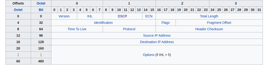
The Internet layer has an IP packet which consists of a header section and a data section as shown in Figure 1. The IPv4 packet header consists of 14 fields, of which 13 are required, as shown in Figure 6. To learn more about IPv4, see here.
Figure 6: IPv4-Header format
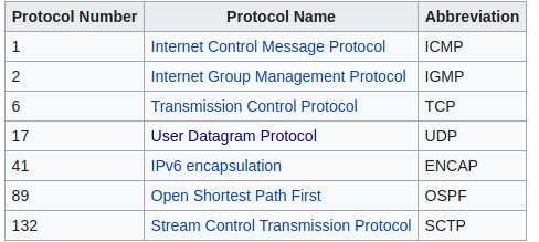
The data section includes the payload protocol embedded within the link layer. There is a protocol number assigned to this section, as shown in Figure 7 below. Per Vices uses 17; i.e. User Datagram Protocol (UDP).
Figure 7: IPv4-Data
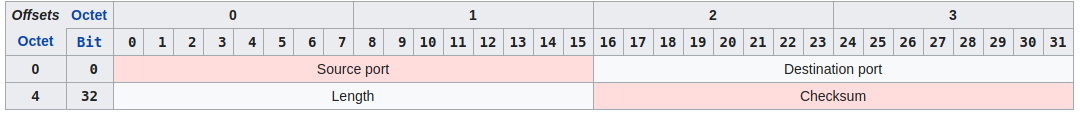
Transport Layer (UDP)
The Transport layer of Figure 1 is where the UDP is found. The protocol consists of the following structure:
Figure 5: UDP-Header
Application (VITA 49 Layer)
Within the Application layer of Figure 1, the VITA 49 data packets are implemented. Importantly, this includes the VITA 49 Packet Header and VITA 49 Data (IQ Pairs). Crimson TNG and Cyan use the following VITA 49 packet types on Tx and Rx, shown in Figure 2 below.
Figure 2: VITA 49 Packet Types
VITA 49 Packet Header
The specific VITA 49 packets that Per Vices support are listed below with a brief explanation:
-
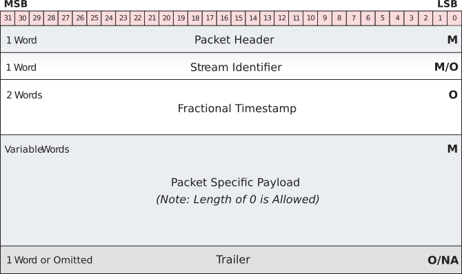
Packet Header: Every VITA 49 packet shall have a header with the following format, shown in Figure 3.
Figure 3: VITA 49 Packet Header

The following are applicable to Per Vices version of VITA 49 32-bit Packet Header:
Table 1: Per Vices VITA 49 Packet Header Word Format & Meaning
Word Value of Bits What does this mean? Packet Type 0000 or 0001 Signal Data without Stream Identifier or Signal Data Packet with Stream Identifier C 0 Does not include the Class Identifier field Indicators (0 or 1)01 Bit 26= Trailer, Bit 25= Not VITA 49 Packet Indicator, Bit 24= Signal Spectrum/Signal Time Data Packet TSI 00 No Integer-seconds Timestamp field included TSF 00 or 11 None or Free Running Count Timestamp Packet Count Varying This increases by one every packet Packet Size Varying This 16-bit field indicates the total number of 32-bit words present in VITA 49 packet, including header, payload, and optional fields -
Stream Identifier: This is a 32-bit number assigned to a VITA 49 Packet Stream. Each packet in the VRT Packet Stream contains the Stream ID for that Packet Stream.
-
Fractional Timestamp: This conveys the Reference Point Time to a high resolution, Per Vices only uses “Free-Running Count” Timestamp. This means that it is zero when it starts and counts by 1 after every sample.
-
Packet Specific Payload: The data being sent or received.
-
Trailer: Currently only applicable to Rx, but all bits are zero.
VITA 49 Payload (IQ Pair Data)
Crimson TNG and Cyan use complex, signed, 32-bit integers to communicate data over the SFP+ ports.
Data are transmitted in IQ pairs. Each IQ pair is 32 bits, with the I and Q components represented by two 16 bit signed integers. The specific format is represented in Table 2. To read this data inside GNU radio, you can use a flow chart similar to that shown in Figure 7.1.
Table 2: IQ Pair Data structure
| Bit Position | 31:24 | 23:16 | 15:8 | 7:0 |
|---|---|---|---|---|
| Representation | Re[7:0] | Re[15:8] | Im[7:0] | Im[15:8] |
Figure 4: Sample GNU Radio data sink, visualizing waterfall data.
2.2. Tx VITA 49 Signal Data Packet Implementation
Multi-channel Tx Sample Capture
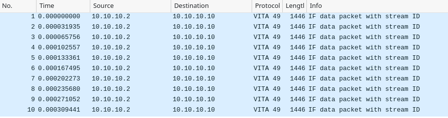
You can download a pcapng capture of 10 Tx packets which were captured using wireshark, and are analyzed below to better illustrate everything in section 2.1., and particularly Table 1: VITA 49 Packet Format.
Figure 9: Capture of 10 Frames from Crimson TNG Tx using Wireshark
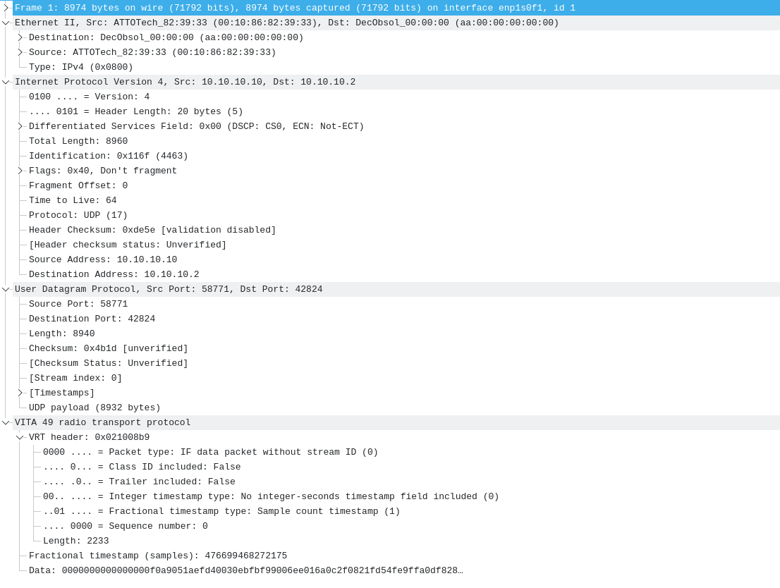
As can be seen in Figure 10 below, where frame 1 was selected, the various layers consisting of the Ethernet, IP, UDP and VITA 49 protocols are decoded. The bits assigned for each protocol agree with what is said in section 2.1., in terms of how VITA 49 Header, IQ data and trailer are in the Application layer, which is then encapsulated in the Transport, Internet and Link layer.
Figure 10: Encapsulation Layers of Crimson TNG Tx Frame using Wireshark
2.3. Rx VITA 49 Signal Data Packet Implementation
Single channel receive PCAPNG sample data
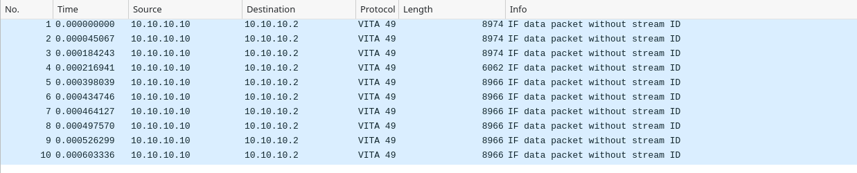
You can download a single channel pcapng capture of 10 Rx VITA 49 packets, which was captured using Wireshark, as shown below.
Figure 11: Capture of 10 Frames from Crimson TNG Rx using Wireshark
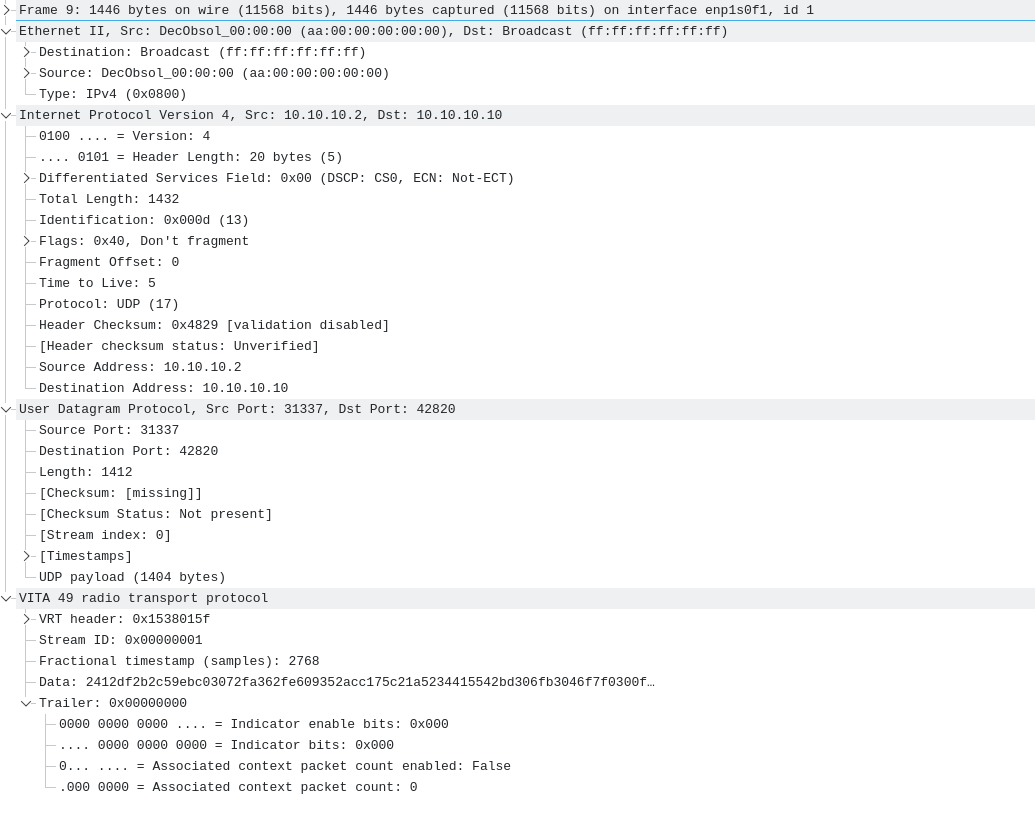
As can be seen in Figure 12 below, where frame 9 was selected, the various layers consisting of the Ethernet, IP, UDP and VITA 49 protocols are decoded. The bits assigned for each protocol agree with what is said in section 2.1., in terms of how VITA 49 Header, IQ data and trailer are in the Application layer, which is then encapsulated in the Transport, Internet and Link layer.
Figure 12: Encapsulation Layers of Crimson TNG Rx Frame using Wireshark
Device Data (Rx)
The following provides actual sample data (IQ pairs) from the device, to assist users with development of their own.
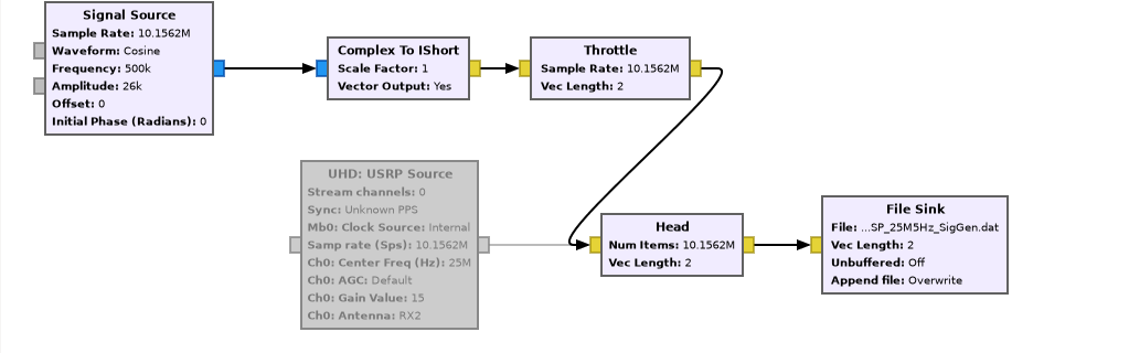
To capture the data, we used a GNU Radio script which was interfaced with Crimson TNG which received a 25MHz signal from a signal generator. You can download the GNU Radio script used to accomplish this. This script provides a means to capture a signal using a GNU Radio signal generator (discussed in subsection below) as well as using an external signal generator with Crimson TNG. Figure 13 below shows how to capture the data using the latter.
Figure 13: Capturing Data using GNU Radio and Crimson TNG Rx

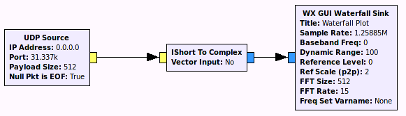
We are then able to use the data within GNU Radio and visualize what was captured. You can download the IQ pair data which was captured using the setup shown in Figure 13. You can also download the GNU Radio script to use this data here. Figure 14 below shows how the GNU Radio script looks, and how to route blocks in order to see the IQ pair data and the frequency we captured.
Figure 14: Using Data to Visualize IQ Pairs and Frequency
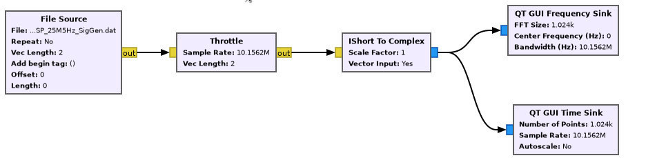
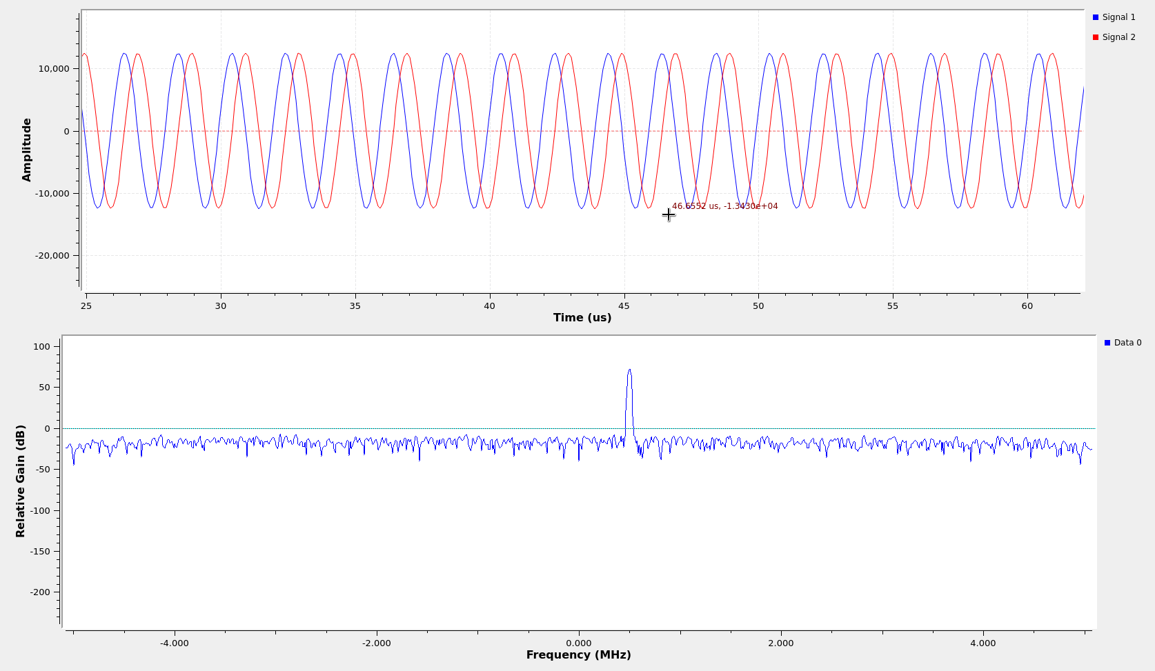
As you can see in Figure 15 below, there are two sinusoidal waves out of 90 degrees out of phase (i.e. a complex valued IQ signal) and the frequency of the signal.
Figure 15: Using Data to Visualize IQ Pairs and Frequency
3. Simulated Sample Generation
You can simulate sample formating using gnuradio.
Rx Sample Simulation
You can also use the GNU Radio script as a sample simulator. Note that all we did was disable the UHD:USRP Source block shown in Figure 13. Figure 16 below shows this.
Figure 16: Simulating Data with GNU Radio
4. Multi-channel receive data
You can download four channels receive data in pcapng format, that was collected using wireshark.
4.1 Multi-channel receive capture
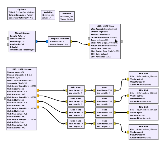
This data was collected using our GRC Phase Coherency Tutorial Script. Figure 17 below shows how simulating and collecting four channels worth of data was accomplished:
Figure 17: Simulating Four Channels of Data with GNU Radio i
To visualize the data, you are able to use a flow graph similar to Figure 14.