IQ Signals and IQ Modulation/Demodulation
The following application note provides an introduction to IQ signals and modulation.
1. On IQ Signals
A complex wave can be represented using two orthogonal value pairs, in the form of IQ signals. These two orthogonal numbers represent a complex waveform with a 90° phase relationship. The \(I\) stands for “in-phase” and \(Q\) stands for “quadrature”. In fact, a consine and sine wave are quadrature waveforms of each other.
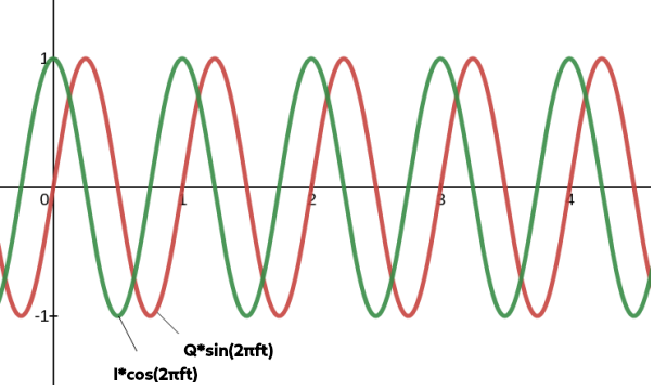
We can say mathematically that our quadrature signal is represented as \(I*cos(2\pi f t)\) and \(Q*sin(2\pi f t)\), where by convention, the \(I\) is the amplitude of the in-phase and \(Q\) is the amplitude of the quadrature components. Figure 1 below shows this:
Figure 1: Basic IQ Signal (With I=Q=1)
1.1 Basics of IQ Modulation/Demodulation
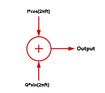
The key to IQ modulation and demodulation is how we add quadrature signals for various modulation schemes. The block diagram below shows how adding \(I\) and \(Q\) works;
Figure 2: Adding Quadrature Signals
As an example, by simply adding the I and Q values together, by superposition, if we were to say \(I=1\) and \(Q=1\), then we’d have a new waveform in black shown below:
Figure 3: Adding the I=1 and Q=1 Signal
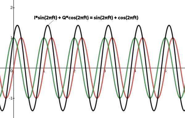
Figure 3: Adding the I=1 and Q=3 Signal
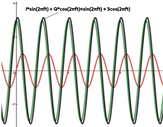
In general, if \(I\) or \(Q\) changes or varies, the result are changes in amplitude, phase and frequency modulation of the sum. Essentially as the \(I\) and \(Q\) vectors change, the magnitude of the vector sum changes. The GIF below shows how this works using a phasor diagram– another way to visualize IQ signals:
Figure 5: How Adding I (x-axis) and Q (y-axis) Changes with a Phasor Diagram
Now, knowing how the complex plane works, and making our IQ signal a function of time, we can see that IQ pairs can be represented by a famous formula, Euler’s formula:
\({e}^{i2\pi f t}= cos(2\pi f t) + isin(2 \pi f t)\)
\(= I(t) + iQ(t)\)
And thus, we say the amplitude vector’s magnitude is given by:
\(A= \sqrt{(I^2 + Q^2)}\)
And the angle \(\theta\) between the I vector and the A vector is:
\(\theta= tan^{-1}(Q/I)\)
1.2 IQ Modulators/Demodulators
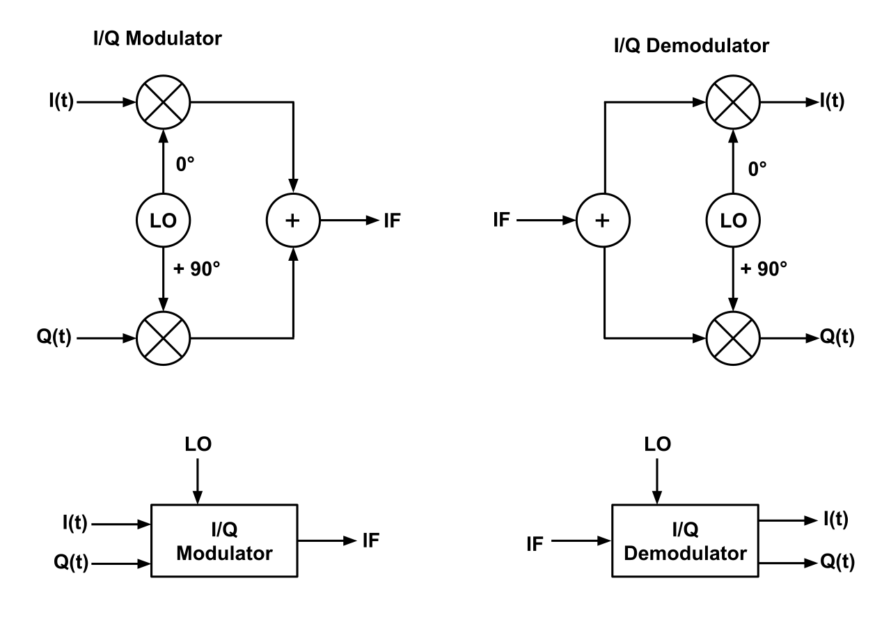
To control how the \(I\) and \(Q\) signals are modulated/demodulated, the use of a IQ modulator and IQ demodulator is needed, which essentially mixes an LO frequency from 0-90° with the \(I(t)\) and \(Q(t)\) signals, as shown in the following block diagrams:
Figure 6: IQ Modulator and Demodulator
2. Further Reading
For other resources on learning about IQ signals and modulation, see these links:
3. Further Videos
Videos by user w2aew on Youtube are also very informative, and can be seen in the links below: