Real world vs. Ideal signals: Mixers, Artifacts, Spurs, IQ Mixer Imbalance, Compression and Intermodulation
1. Purpose
In this application note, we discuss how “real world” signals differ from “ideal signals”, and how they apply to our software defined radio (SDR) systems. We will first cover the basics of the various mixers we use in our SDR and then mixing artifacts, spurs, IQ imbalances, compression and intermodulation (i.e. phenomenon which will also appear besides your desired or “ideal” signal). Much of these phenomenon can limit the dynamic range of the system.
2. Basics of Mixers
While mixers all have the same principles behind them, i.e. to upconvert or downconvert a signal while preserving phase, amplitude and other wave characteristics (and ideally minimal conversion loss between the input RF and output IF power level), there are various types of mixers we use in our SDRs. This includes real mixers, complex IQ mixers, and also digital (CORDIC) mixers. Moreover, there are various ways to construct a mixer circuit (passive and active), which are most often Schottky diodes, GaAs, FETs and CMOS transistor based circuits. Without going into too much depth, here we briefly discuss how the various mixers in our SDR work before discussing the implications of this in the next section.
Generally, there are three ports on a mixers which are used for either upconversion or downconversion, and they are labelled:
Downconversion
-
RF: this is the input, generally from an antenna, that you are looking to downconvert into IQ pairs.
-
LO: this is the ‘local oscillator’ input signal you’re mixing with the RF, and generally corresponds to the desired input RF center frequency.
-
IF: this is the output downconverted signal, which, we assume to be in the form of an IQ pair.
Upconversion
-
LO: this is a ‘local oscillator’ input that is mixed with the IF, and corresponds to the frequency you would like to transmit at.
-
IF: this is the signal you’re looking to upconvert which is mixed with the LO, and in our case, these are IQ pairs.
-
RF: this is the output of the mixed IF and LO
2.1 Real RF Mixers
-
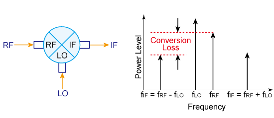
Downconversion is the process of mixing an RF input and LO to obtain an output IF lower than the RF input. Described below is single band downconversion:
\[ f_{IF}= \mid f_{LO} -f_{RF} \mid \] -
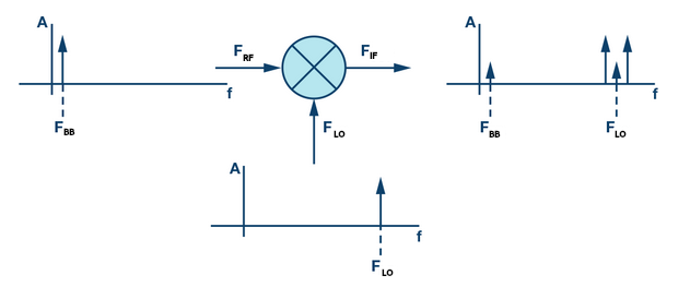
Upconversion is the process of mixing an LO such that RF output is larger than the RF input. The type of upconversion described here is double sideband upconversion:
\[ f_{RF_1}= f_{LO} - f_{IF} \]\[ f_{RF_2}= f_{LO} + f_{IF} \]Figure 1: Downconversion and Upconversion (Source: https://www.digikey.ca/en/articles/the-basics-of-mixers)
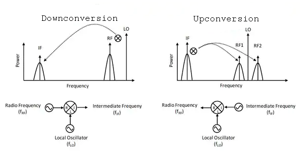
In Figure 1 above, the two bands on either side of the LO are referred to as sidebands (i.e. two regions where the upconverted RF signal is). We tend to refer to the (left) lower sideband of the LO as the image sideband. Often, you only want one sideband, and you need to somehow filter or cancel out the other. In upconversion, we can accomplish this by using a standard mixer with a filter, or a single side-band (SSB) mixer using a Hartley modulator, which will use phase manipulation and thus eliminates the need for a narrow-band filter to take out the unwanted sideband. For downconversion, the use of a standard mixer with filter, or image reject (IR) mixer, will allow for the removal of the unwanted images. IQ mixers go a step further, and allow you to filter out this image within the mixer itself, as will be explained below.
2.2 Complex IQ Mixers
Note
For an introduction to IQ signals and IQ modulation/demodulation, see here.
An IQ mixer consists of two mixers where the RF (or LO) ports are connected with an in-phase power divider and the LO (or RF) ports are connected with a quadrature hybrid. The two IF ports, \(I\) for the in-phase component and \(Q\) for the 90° out-of-phase component, are available to the user. This combination allows the in-phase and quadrature components of the output signal to be modulated independently with each IF port. IQ mixers use phase manipulation to suppress unwannted signals instead of expensive filters commonly used, as described in section 4.
Figure 2: IQ Mixers (Source: https://www.markimicrowave.com/blog/how-to-think-about-iq-mixers/)
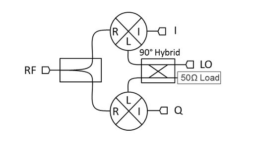
An IQ mixer can be understood by observing the schematic in Figure 6 above. Essentially, it consists of two regular mixers and a quadrature hybrid coupler at the LO. The hybrid coupler splits the signal of the LO into two output ports, with a phase shift of 90° �in one of them. In upconversion, each of these outputs is either mixed with the \(I\) signal or the \(Q\) signal and then both outputs are combined in the RF port. On the other hand, if the mixer is used for downconversion it will allow to retrieve both \(I\) and \(Q\) original data signals in the RF input.
How this works to suppress sidebands is discussed in below in subsection 3.2.
2.3 CORDIC Mixers
When our signals are in the digital domain, the use of COrdinate Rotation DIgital Computer (CORDIC) is used. Essentially, a CORDIC is a class of shift-add type algorithms for rotating vectors. Vector rotation is the basis of computing magnitude and phase relationships of input vectors and various digital signal processing (DSP) applications such as discrete Fourier transforms (DFT) and of course, mixers.
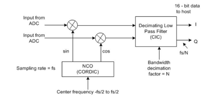
Both Crimson TNG and Cyan have CORDIC digital mixers that are capable of both up-conversion and down-conversion (DDC, DUC). In the Tx chain, upconversion is accomplished by mixing the Tx samples with a local oscillator found in the FPGA (set to what is referred to as the NCO frequency). This causes the frequency of all our signals to increase. Using the larger conversion bandwidth that we obtained from interpolation ensures that we can capture more of our mixing products. This also produces image signals via image wrap-around and is a fundamental and expected outcome of the Nyquist theorem. In the Rx chain, down-conversion is accomplished by mixing the Rx samples with a local oscillator found in the FPGA (set to what is referred to as the NCO frequency). Decimation further downsamples the signals and dictates the final user bandwidth before proceeding to the host computer/application. The basic architecture of our CORDIC DDC mixer is shown in Figure 3.
Figure 3: Direct Down Converter CORDIC Mixer (Source: https://citeseerx.ist.psu.edu/viewdoc/download?doi=10.1.1.519.6325&rep=rep1&type=pdf)
3. Mixing Artifacts
The mixer ports, as shown in the bottom half of Figure 1, are designed using circuit symmetry, such as a hybrid junction or combination of these, to balance the mixer (i.e. create isolation among ports, cancel intermodulation mixing products, and so on). Still, however, there are noticeable artifacts in the frequency domain such as LO feedthrough, IF feedthrough, and sideband/image formation.
3.1 LO Feedthrough
One consequence of not having perfect isolation (i.e. parasitic capacitance, power supply coupling, etc.) is that of LO feedthrough. Feedthrough or leakage into the mixer ports exists in all combinations– i.e. LO-RF (reverse LO feedthrough) and LO-IF, and is therefore noticeable in the frequency domain.
Figure 4: Ideal Mixer Frequency Plot with No LO Feedthrough (Source: https://www.analog.com/en/analog-dialogue/articles/transmit-lo-leakage-lol-an-issue-of-zero-if-that-isn-t-making-people-laugh-out-loud.html)
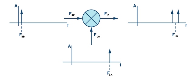
Figure 5: Real-World Mixer Frequency Plot with LO and RF Feedthrough
The ideal mixer, as shown in Figure 4, shows a frequency domain plot where there is no LO at the output RF frequency. However, this is not possible in the real-world, and so the frequency domain will often show leaking or feedthrough of the LO frequency as well, as shown in Figure 5. While our \(F_{BB}\) signal can be filtered out, as it’s far from the desired output, the \(F_{LO}\) is not, and will therefore be present.
Further reading:
3.2 Images/Sidebands
During upconversion in the Tx chain or downconversion in the Rx chain, an image frequency is generated where the desired \(f_{IF}\) or \(f_{RF}\) is located, as in Figure 5. With real mixers, we often use a filter to get rid of the image sideband if it’s not within our desired signal bandwidth. However, in practice, this is not possible, and we want to suppress this image by employing phase cancellation during mixing/conversion (i.e. ‘direct conversion’).
In IQ Mixers, images are substantially eliminated during image reject (IR) downconversion of an IQ mixer, or by using a single sided upconversion or single sided downconversion mixer. All of these essentially involve phase cancellation schemes. Here we will only show how single sided downconversion achieved only one sideband, as in the top left of Figure 1 (note: we could do this with sine and cosine complex identities but will omit this for brevity).
Assuming that our mixers act as perfect multipliers, and our signals have amplitude of 1, \(I=cos(2 \pi f t)\) and \(Q=sin(2 \pi f t)\), we can mix \(I\) with \(cos(2 \pi f_{LO}t)\) and \(Q\) with \(sin(2 \pi f_{LO}t)\), and use the sum/difference trigonometric identities to obtain the following:
\(cos(2 \pi f t)cos(2 \pi f_{LO}t) + sin(2 \pi f t)sin(2 \pi f_{LO}t)= cos(2 \pi t(f - f_{LO})) =\) lower sideband
OR
\(cos(2 \pi f t)cos(2 \pi f_{LO}t) - sin(2 \pi f t)sin(2 \pi f_{LO}t)= cos(2 \pi t(f + f_{LO})) =\) upper sideband
Thus, only the lower or upper sideband appears, and the other cancels, depending on the LO phase.
For more on how images are suppressed, see here.
3.3 Expected Spurs
A microwave or RF mixer will produce not only the desirable \(1 f_{RF} \times 1 f_{LO}\) frequency product, it will also produce every arithmetically possible frequency component. Any frequency expressed as \(m f_{LO} + n f_{RF}\) will show up as an output of the mixer. All products besides the desired 1x1 product are called ‘spurious’ mixer products, or spurs for short. Most mixer circuits will suppress many of these spurious products by using balancing techniques. However, at certain tuning and LO frequencies, these will appear in your frequency spectrum.
Marki Microwave provides an excellent spur calculator.
4. IQ Imbalance
In this section we discuss all these issues and how they relate to complex IQ mixers. Any imperfection in the phase balance of the LO or the amplitude or phase balance of the I/Q channels will lead to imperfect cancellation of the sidebands in a single sideband (SSB) or image reject (IR) mixer, or imperfect rejection of the unwanted channel in an IQ mixer. This includes any imperfection in the phase and amplitude balance of the baluns that constitute the double (or more) balanced mixer cores of an IQ mixer that leads to increased LO feedthrough, RF/IF feedthrough, and spurious products.
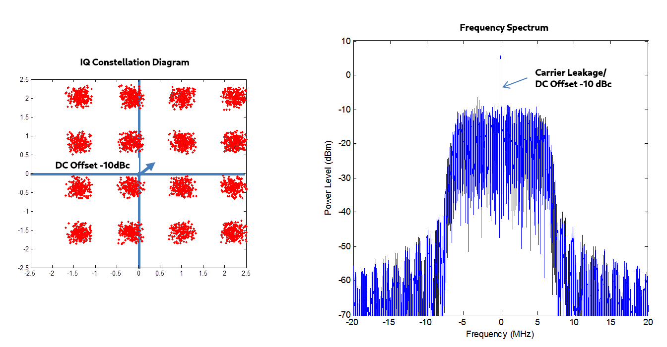
4.1 DC Offset
A DC offset between the \(I\) and \(Q\) waveform is an conversion loss imbalance between the two mixers inside the IQ mixer. The main consequence is that when performing upconversion with the IQ mixer a certain amount of the LO signal will leak in the mixer RF output. The LO to RF isolation, one of the metrics of an IQ mixer, quantifies this carrier leakage. This offset will introduces carrier/ RF leakage into the frequency domain plot of our signal. It will thus cause issues for us when performing IQ modulation/demodulation.
Figure 6: DC Offset on a 16-QAM (Source: https://dsp.stackexchange.com/questions/40734/what-does-correcting-iq-do)
4.2 IQ Phase Mismatch/Imbalance
Physically, phase imbalances are due to phase balance issues of the hybrid coupler and different electrical connection lengths. This imbalance is indicated by the quadrature phase deviation of the mixer. Because of both of these imbalances the cancellation of the unwanted sideband will not be perfect.
The phase will always vary more with higher frequency IFs than with lower frequency IFs due to the same time delay becoming a greater phase delay at high frequencies, as shown in Figure 7.
Figure 7: Phase Delay Errors (Source: https://www.researchgate.net/figure/llustration-of-phase-imbalance-at-low-and-high-frequency-due-to-a-mismatch-induced-timing_fig3_288871511)
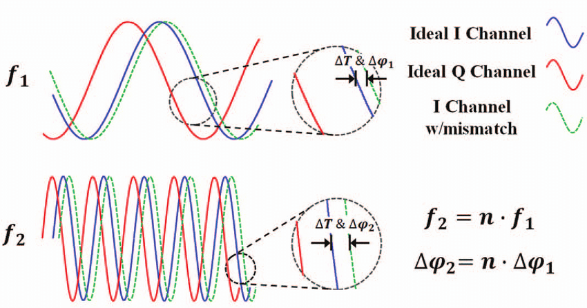
For example, a mixer with a constant \(\Delta \psi_1=5\) degree phase delay error (i.e. independent of frequency) at \(f_1=100\) MHz, will at ten times (\(n=10\)) the frequency of \(f_1\) become \(f_2=n*f_1= 1000\) MHz with a phase mismatch of \(\Delta\psi_2=n*\Delta\psi_1=50\) since the period is 10 times shorter.
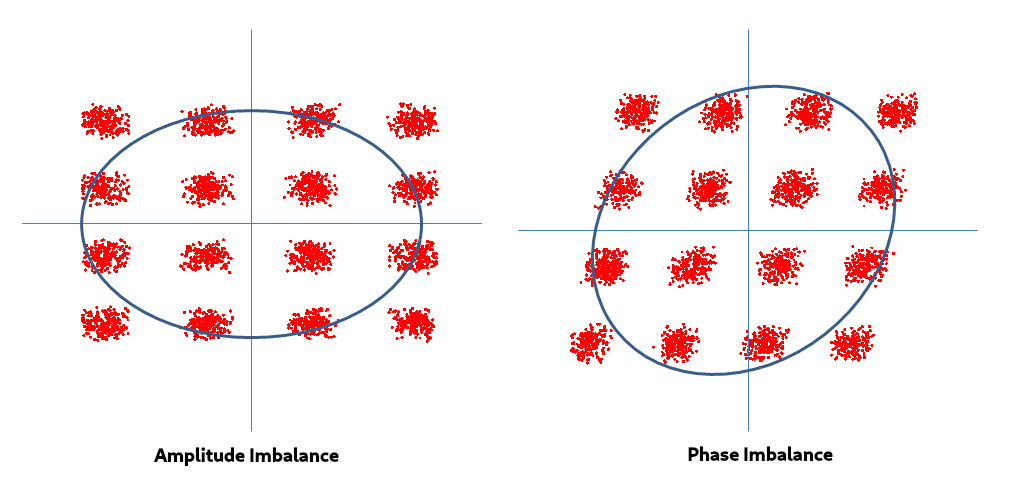
The effect of this can be seen in constellation diagrams, where deviation between a modulation schemes ideal points and those found in the real world– i.e. error vector magnitude (EVM). Figure 8 below shows this:
4.3 IQ Amplitude Mismatch/Imbalance
Amplitude (gain) imbalances are physically caused by imbalances in the quadrature hybrid coupler and different conversion losses in each of the mixers in the IQ mixer. This entails that the amplification/attenuation through the IQ mixer of each of the signals is not identical. The amplitude deviation of a mixer is the metric which quantifies this amplitude imbalance.
The ramifications of IQ amplitude imbalance is particularly noticeable when observing a constellation diagram of a modulation scheme. When there is signifcant amplitude imbalance, error vector magnitude (EVM) becomes particularly prominent.
Figure 8: Effect of Phase and Amplitude Imbalance on a IQ 16-QAM Constellation Diagram (Source: https://dsp.stackexchange.com/questions/40734/what-does-correcting-iq-do)
5. P1dB Compression
Mixers, under normal linear operation, are excellent frequency converters such that every dB change in input power results in a dB change in the output power, and the conversion loss (CL) of the mixer will be constant, regardless of input RF power. Thus, if the input RF power increases by 1 dB, then the output IF power will also increase by 1 dB (the power difference is the conversion loss in logarithmic units). Mathematically, we can say the conversion loss is:
\(CL = 10\log_{10}(\frac{P_{RF}}{P_{IF}})\) , where units are in dB
OR
\(CL = P_{RF} - P_{IF}\) , where units are in dBm
Figure 9: Conversion Loss (Source: https://ena.support.keysight.com/e5071c/manuals/webhelp/eng/measurement_with_options/frequency_offset_measurement/measurement_of_mixers.htm)
However, as the RF power becomes too large when entering the mixer, this dB for dB relationship will not hold. The 1 dB compression point is a measure of the linearity of the mixer and is defined as the input RF power required to increase the conversion loss by 1 dB from ideal. The conversion loss will begin to increase and thus non-linearity ensues. The 1 dB compression point is therefore defined as the RF input power required to cause the conversion loss to increase by 1 dB. This compression point is the maximum recommended RF input power to the mixer.
Figure 10: Plot showing a Mixer P1dB Compression
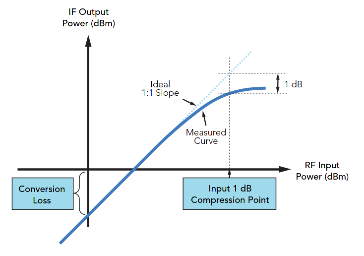
Physically, for Schottky diode mixers, compression arises when the input RF signal begins to challenge the turn-on potential of the diodes. When this happens, the mixer fails to act as an LO controlled switch (i.e. the voltage applied does not cause current to flow in the diode), and the desired mixer behavior degrades. In order to prevent the RF signal from acting as the LO, the Schottky diode barrier must be increased such that the RF signal becomes too weak to switch the diodes ON and OFF.
6. Intermodulation Distortion and Third Order Intercept Point (IP3)
Intermodulation occurs when two or more signals arrive at the input of a mixer. The intermodulation frequencies are generated because of the nonlinearity of a mixing device, as explained in the P1dB section above. As we know from mixing two signals \(f_1\) and \(f_2\), they will appear in the frequency domain as the sum \(f_1 + f_2\) and difference \(f_1 - f_2\). Moreover, harmonics of these frequencies also appear, i.e. \(2f_1\) and \(2f_2\) mixed in various combinations with \(f_1\) and \(f_2\). The order of the harmonics is determined by the sum of the absolute value of the coefficents of these products. For instance, \(2f_1\) and \(f_1 + f_2\) are second order, whereas \(2f_2 + f_1\) are third order. Figure 11 shows this. Often times, these mixing products, harmonics and intermodulation frequencies are unwanted signals, and thus we call them intermodulation distortion (IMD).
Figure 11: Harmonics and Intermodulation Products (Source: https://www.everythingrf.com/community/what-is-intermodulation-distortion)
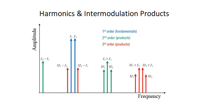
While the harmonics tend to drop off in amplitude as the order increases, as well as the ability to attenuate or filter out these unwanted signals, problems still arise with third order intercept points. This is illustratd in Figure 11 above, as we see that the third order harmonics \(2f_1 - f_2\) and \(2f_2 - f_1\) are quite close to our fundamental frequency and thus generally within the bandwidth of the fundamentals. Making matters worse, the third order harmonics increase at the output by 3dB for every 1dB input, whereas the ideal fundamental increases linearly by 1dB input for 1dB output, as shown in Figure 12 below.
Figure 12: First (Fundamental) and Third Order Input vs. Output power (Source: https://rf-tools.com/ip3/description.html)
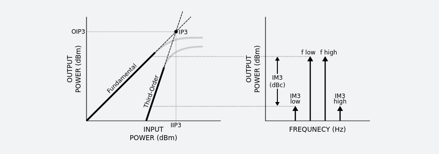
In reality, the fundamental and third order products approach the 1dB compression limit, and thus the third order signal will not be larger in amplitude than the fundamental. However, we can imagine that the lines for the fundamental and third order products extend until they intercept, giving what is referred to as the third order intercept point (IP3 or TOI). While this is a theoretical value, often we hear of this as a measureble quantity. In practice, the TOI or IP3 is a measure of the linearity of the device: a higher TOI or IP3 indicates that the device is more linear and suffers less intermodulation distortion.
For further reading and to see how this is measured, see the following: